White paper – story of success
Ring inductor for a gear ring
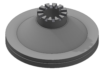
For a new hardening zone on a gear ring, see Figure 1, we had many ideas how to harden the tooth area. However, we wanted to try out different options without creating great expenses and meet the hardening zone requirements right with the first inductor built.
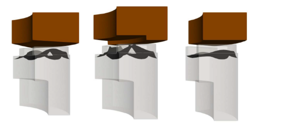
In a first step three different inductor designs were created and simulated with the software CENOS.
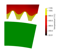
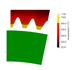
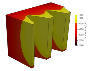
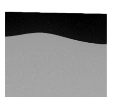
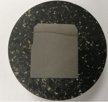
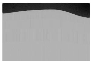
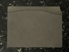
Figure 4: Comparison of the hardening zone in the tooth (left) and tooth root (right) with the simulation. On the left sketch of each pair, the black area represents the material that has been heated above AC3 temperature
The hardening zone of the simulation matched well with the simulated 3D model, see Figure 4.
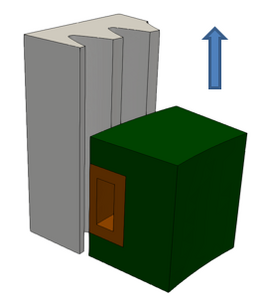
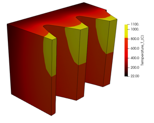
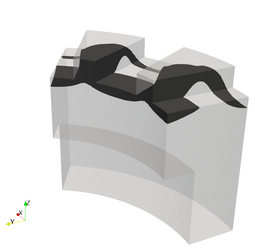
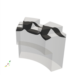
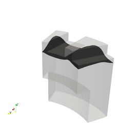
The hardening zone for an inner gear ring also included the tooth root. The hardening process was a scanning application with rotation. Because of the radial symmetry, only an angular section was simulated as shown in Figure 5. First simulations showed that with just one heating pass, only the tooth body would be hardened, but not the tooth root. The final solution, both in simulation and production, was a preheating pass followed by a hardening pass.
SMS Elotherm is able to develop inductors for new hardening zones without great expenses and set up more advanced heat treatment approaches that greatly reduce the development efforts during the following lab trials or even allow us to forego on trials.



![[Translate to Chinese:] [Translate to English:] Abbildung 5: Innerer Zahnkranz](/fileadmin/_processed_/3/6/csm_Ringinduktor-1_58a5bd130b.png)
